...
A requirement of IVI systems is that they need to support transitions to multiple power states. Not just a simple power off/on state, but several other types of power states are required. In each power state, it is necessary to switch the function to be controlled and the power state of connected devices.
Due to the diversity of use cases in modern automotive, it is necessary for IVI systems to operate even in situations where there is no voltage supplied by the battery. A problem inherent to IVI is the limited power supplied by the battery. If you always start and maintain any hardware in the state, it will lead to battery failure. Therefore, when using IVI, it is necessary to define the various power states according to the use case of each user, and in each power state, activate the minimum amount of hardware necessary to realize the use case and realize the function.
...
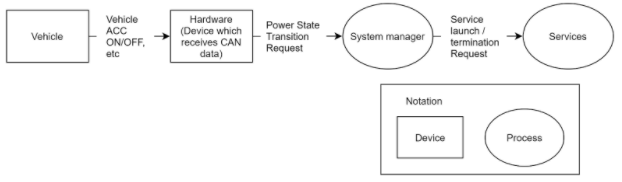
The description of Hardware in 4.4 section indicates some kind of hardware (such as CAN signal) that notifies the IVI side of power state transition.
Figure1
Use cases
In the following table, use cases which need the Power State Management function are described. In each use case, a power state transition of the car is changed, and the IVI also needs to change states.
Table 2
# | Item | Description |
|---|---|---|
UC.PS.1 | IVI(quick) startup | The driver opens the door and gets into the car. And the driver user presses the button for ACC-ON and the car and the IVI is turned on. |
UC.PS.2 | IVI shutdown | The driver presses the button for ACC-OFF, gets out of the car and does not get into the car for a long time. |
UC.PS.3 | Startup unlinked with the ACC | The driver presses a button for IVI-ON and uses audio, video, and communication services without ACC-ON. |
UC.PS.4 | Delayed ending | After arrival at the destination, when the driver wants to continue a handsfree call after ACC-OFF, the driver user continues it although the display is off. |
UC.PS.5 | Remote parking system | When the driver wants to get the car out of the parking lot, the driver uses the smartphone-linked function to control outside and gets into the car. |
UC.PS.6 | Demotion assistance | After the driver arrives at the destination, the driver presses the button for ACC-OFF and gets out of the car. When the driver gets out of the car, if there is danger behind the car, an alarm sounds and the driver is notified. |
UC.PS.7 | Return to the car soon | The driver presses the button for ACC-OFF, gets out of the car and gets into the car soon. |
UC.PS.8 | Return to the car temporally | The driver opens the door and takes out the luggage. The driver closes the door and does not get into the car. |
UC.PS.9 | Automatic updates via OTA | IVI automatically updates software through OTA function while the driver is away from the car. |
UC.PS.10 | Data backup | IVI performs data backup while the driver is away from the car. |
...
The following shows the IVI state transition diagram of the above table. The conditions for each transition are also described.
Figure 4 ) State transition diagram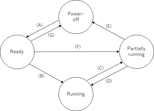
When the power status of the vehicle changes, the power status of the IVI will transition.
...
Use case | State transition diagram | The condition of transition |
|---|---|---|
(1)IVI (quick) startup | (A), (B) | (A)The transition request to change the selected services states to “Ready” is sent from the Hardware side. (B)The transition request to change the IVI state to “Running” is sent from the Hardware side. |
(2)IVI shutdown | (C), (E) | (C)The transition request to change the IVI state to “Power-off” is sent from the Hardware side. (E)When no transition request is received and a certain amount of time has passed, the state is changed. |
(3)Startup unlinked with the ACC | (A), (F) | (A)The transition request to change the selected services states to “Ready” is sent from the Hardware side. (F)The transition request to change the selected services states to “Partially Running” is sent from pressing a button for IVI-ON. |
(4)Delayed ending | (C) | (C)When the transition request to change the IVI state to “Power-off” is sent from the Hardware side, the state goes through “Partially running” once. If there is a request to execute the function, it is done in this state. |
(5)Remote parking system | (A), (F) | (A)The transition request to change the selected services states to “Ready” is sent from the Hardware side. (F)The transition request to change the selected services states to “Partially Running” is sent from the user’s smartphone. |
(6)Demotion assistance | (C) | (C)When the transition request to change the IVI state to “Power-off” is sent from the Hardware side, the state goes through “Partially running” once. If there is a request to execute the function, it is done in this state. |
(7)Return to the car soon | (C), (D) | (C)The transition request to change the IVI state to “Power-off” is sent from the Hardware side. (D)The transition request to change the IVI state to Running is sent from the Hardware side. |
(8)Return to the car temporally | (A), (G) | (A)The transition request to change the selected services states to “Ready” is sent from the Hardware side. |
(9)Automatic updates via OTA | (A), (F), (E) | (A)The transition request to change the selected services states to “Ready” is sent from the Hardware side. (F)The transition request to change the selected services states to “Partially Running” is sent from pressing a button for IVI-ON. (E)When no transition request is received and a certain amount of time has passed, the state is changed. |
(10)Data backup | (A), (F), (E) | (A)The transition request to change the selected services states to “Ready” is sent from the Hardware side. (F)The transition request to change the selected services states to “Partially Running” is sent from pressing a button for IVI-ON. (E)When no transition request is received and a certain amount of time has passed, the state is changed. |
...
This table includes the functional requirements of Power State Management module. Figure1 will be used to explain this requirement.
Table 6
# | Item | Related use case | Description |
|---|---|---|---|
FR.PS.1 | Power state receiving | All of the use cases | Power State Management should receive state transition requests from the Hardware side. |
FR.PS.2 | The incoming trigger of the power state depends on each OEM so the incoming trigger should be flexible enough to change. | ||
FR.PS.3 | Power state sending | Power State Management should notify the power state change request to each service. | |
FR.PS.4 | Since the number(definition) of power states depends on each OEM, adding or removing power states should be flexible enough to change. | ||
FR.PS.5 | Only services which require control by power state change requests should be notified of the necessary request. | ||
FR.PS.6 | Device control | According to the power state transition, each application or middleware related to services should switch the function to activate or the control devices. |
...
Reference implementation by Basesystem
To have Power State Management for the use cases above, we provided the following functions as part of the power management function. Refer to the software configuration diagram(2. The scope).
- Power Service
- System Manager
In the implementation of Basesystem, the function modules for Power Service Management are Power Service and System Manager. The software configuration diagram is defined in 2. The scope. Please refer to it.
Figure 7![]()
...
Power service provides functions such as notifying the system manager unit module of power state transition requests by getting the notification from the Hardware side, or receiving requests and notifying the Hardware side of it.
...
In order to control the system according to the power state transition request, System manager notifies the services on the service list of a power state transition received from Power service.
Reference Code
...
Reference code :
https://gerrit.automotivelinux.org/gerrit/gitweb?p=staging/basesystem.git;a=tree;f=service/system/system_managerpower_service;h=fabcbf6aabbf0b7dd8a1df2fb35491029a2d1fdd;hb=refs/heads/master
System Manager
In order to control the system according to the power state transition request, System manager notifies the services of a power state transition received from Power service.
Reference code :
https://gerrit.automotivelinux.org/gerrit/gitweb?p=staging/basesystem.git;a=tree;f=service/system/power_service;h=fabcbf6aabbf0b7dd8a1df2fb35491029a2d1fddsystem_manager;hb=refs/heads/master