Abstraction
If the IVI system should detect some kind of failure and determine that the system can no longer maintain normal state, simply rebooting the system and waiting for it to recover is not enough in terms of convenience and safety for users. This is because freezing the screen for a few seconds while driving and just waiting for the system to reboot can cause a very dangerous situation for the user.
Therefore, when the IVI system detects such failure, a recovery procedure needs to be performed. For example, restarting the service that caused the problem, or restarting the entire system. They will prevent the system from continuing in an abnormal state and minimize the negative impact on users.
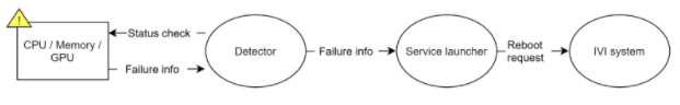
The following figure shows the roles of the modules that perform detection when a failure is detected and the data flow diagram. Figure shows a case where a failure such as a service hang-up occurs, and Figure 2 shows a case where a failure such as a shortage of resources such as memory occurs. In the IVI system, each service in the IVI system needs to be monitored by heartbeat communication, etc. The Detector monitors the service and when it detects a failure, it notifies the service launcher of the information and sends a request to the service to restart or to restart the entire IVI system to bring the system back to a normal state. System resources(in this case, Memory, CPU, and GPU) need to be monitored as well. If the Detector monitors the resources and detects a failure, it will take the same steps to recover.
The functions of failure detection defined in this chapter shall cover the following.
- Detection of failures that occur when service startup or termination
- Detection of failures that occur in resources(System memory, CPU and GPU)
The recovery process is defined for these failures as follows.
- Restart the service
- Restart the system
- Keep a system error log
As described above, this chapter describes the use cases that require the failure detection service, the functional requirements to handle the use cases, and the current Basesystem design and implementation as a reference.
Figure 1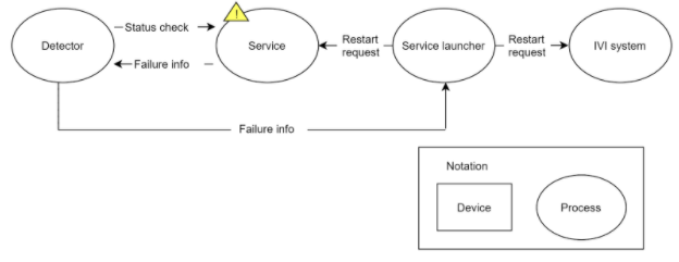
Figure 2
Use cases
In the Table 17, use cases which need System Failure Detection and Procedure when the IVI system is operated are described. The use cases UC.FD.1 to UC.FD.4 are for the passenger to face the navigation app failures, and UC.FD.5 is for OEM to analyze the failure at a service station later.
Table 3
| # | Item | Description |
|---|---|---|
UC.FD.1 | Service failure at System startup | The passenger is not able to see the map image on the screen, e.g. the map service cannot be activated. |
UC.FD.2 | Service failure when System is in use | The passenger is not able to see the map image on the screen due to the route calculation, guidance services, etc. not responding. |
UC.FD.3 | System memory shortage detection | The map image on the screen has freezed and not been updated due to a shortage of system memory. |
UC.FD.4 | CPU/GPU high load detection | The navigation map app does not respond in expected time and shows intermittent image updates due to very high work-load of system resources. |
UC.FD.5 | CPU/GPU usage log | In case of poor usability, i.e. intermittent screen updates, the IVI system resource information is recorded for OEM to analyze the issues later. |
Functional Requirements
This table shows the functional requirements of Service Failure Detection module. It is assumed that the targets of failure detection are Services, system memory resources, CPU work-load, GPU work-load.
Table 4
| # | Item | Description | Description |
|---|---|---|---|
RQ.FD.1 | Service failure detection | UC.FD.1,UC.FD.2 | The detector shall monitor IVI service health status. If an IVI service does not respond, it shall be recognized the service is in failure status. |
RQ.FD.2 | Timeout parameter for service monitoring | UC.FD.1,UC.FD.2 | The timeout parameter shall be configurable for the detector to wait for the response from an IVI service. |
RQ.FD.3 | Frequency for service monitoring | UC.FD.1,UC.FD.2 | The frequency with which the Detector checks the service should be configurable. |
RQ.FD.4 | Memory failure detection | UC.FD.3 | The detector shall decide the system is in failure status if the system memory consumption exceeds the threshold for the specified periods. |
RQ.FD.5 | CPU / GPU failure detection | UC.FD.4, | The detector shall decide the system is in failure status if the GPU work-load exceeds the threshold for the specified periods. |
RQ.FD.6 | Resource failure detection periods for Memory / CPU / GPU usage | UC.FD.3,UC.FD.4 | The periods to detect the system resource failure in RQ.FD.3 and RQ.FD.4 shall be configurable. |
RQ.FD.7 | System/service recovery | UC.FD.1,UC.FD.2,UC.FD.3,UC.FD.4 | In case of RQ.FD.1, the detector shall perform the system/service recovery operation, if it detects any system failure. |
RQ.FD.8 | Logging of failure | UC.FD.5 | The detector shall record the diagnostic information, e.g. process information, if it detects CPU/GPU resource failure. |
RQ.FD.9 | Immediate service shutdown | UC.FD.1,UC.FD.2,UC.FD.3,UC.FD.4 | The detector shall notify immediate shutdown of the failure service to the terminator if it detects any service failure. |
Service Launch / Termination in Basesystem
Reference implementation in Basesystem
In the implementation of Basesystem, the function modules for Service Failure detection are System manager and Resource manager.
System manager
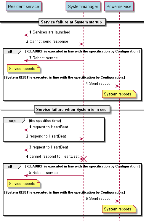
When System manager detects failures on services, it executes the various failure procedure. The contents of the failure procedure are statically prescribed in the Configuration file in advance. The prescribed ones are the system restart and the restart the process in which the failure occured.
System manager monitors the system memory in cooperation with Resource manager. If a notification is received from Resource manager, it recognizes the system memory shortage and resets the system.
Reference code : https://gerrit.automotivelinux.org/gerrit/gitweb?p=staging/basesystem.git;a=tree;f=service/system/system_manager;hb=refs/heads/master
The following sequence diagram(Figure 19) shows the sequence of events when a failure occurs in the system as a sample.
Figure 5
Resource manager
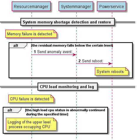
Resource manager is a function that checks the status of the CPU and keeps a log of the high-level processes occupying the CPU if the high-load status continues for a certain period of time. It also checks the status of memory, and if the residual memory gets lower than a certain level, it determines it to be an abnormal state and notifies the System manager.
Reference code : https://gerrit.automotivelinux.org/gerrit/gitweb?p=staging/basesystem.git;a=tree;f=service/system/resource_manager;h=ab341007c7257d839fb6b91b02444675b9de6d60;hb=refs/heads/master
The following sequence diagram (Figure 19) shows, as a sample, the sequence of events when a memory or CPU failure occurs.
Figure6
1 Comment
Riku Nomoto
The memo that were pointed out at Virtual Workshop.
#
Item
#2 is too wide, can be breaking down into more anomaly modes.
(relationship with framework to resume stopped services)
notification after anomaly detection
low-level service anomaly vs high-level app anomaly
#
Item
other hardware device resources, vms, containers (CPU/mem/net/storage)
→ cgroup